Non-isolated LED lamp teardown and modifications.
Introduction
This article adds more detail to the youtube video that just didn't make it into the video. The goal here is to show how these non-isolated high side LED drivers work in general, this specific light is not that important. If you have a chance to design a circuit like this, or modify one, this article will give some information of where to start.

AC Input Circuitry
The chip is very similar to the LYT1402-1604 which I found on Digi-key. This appears to be a pretty common architecture. Let's start with the AC-input circuitry.
The circuit is rated up to 277VAC according to the manufacturer, which is above most voltages seen in residential settings in North America. As such, we have to consider the events that would cause that MOV to see such a voltage. The event where the MOV will see a very high voltage for sustained periods of time would be lightening strikes, transformer failure, or high voltage overhead lines falling on lower voltage lines.
When the MOV sees a high voltage the hope would be that it would trip and blow the 15A breaker of the AC circuit it is running from. However that's a lot of beans, there is a good chance the MOV will vaporize or burn first. So I think it's safe to say the design intent here was to protect against small transients that might damage the switching circuitry, but very large transients are not expected.
My preference would be to put the MOV after the fusible resistor, however in this design they have two fusible resistors, and therefore would need two MOVs. They have decided to save costs with a single MOV. The datasheet for the LYT1402-1604 suggests such an architecture, even pulling the MOV after the bridge rectifier:

Let's also talk about the capacitor, it's an X type EMI capacitor intended to prevent EMI from the DC-DC from radiating back out the AC line and neutral. The fusible resistors and the capacitor form an RC filter circuit that eats up high frequency switching noise. The capacitor must be an "X" type, which is physically designed to be more reliable and not catch fire. Moving on to the DC-DC section.
DC-DC Circuitry
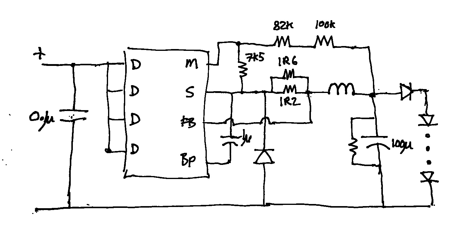
There are a few things I don't like about this circuitry:
- The input capacitor is far too small, the lamp will flicker at 120Hz,
- The BP Bypass capacitor is well below recommended from the datasheet,
- The voltage feedback network of the 100K 82K and 7k5 resistors mean that the open-circuit voltage of the DC-DC at 103V is way too high for the LED string,
- I feel that the brightness can be turned down to promote a longer life of the LEDs.
- Input capacitor to 100uF 250V to elimante 120Hz flicker,
- Bypass capacitor to 4.7uF ceramic,
- Adjusted the voltage feedback network to 72V by changing the 82K resistor to 27K,
- Lowered the brightness by paralleling two 3R2 resistors in place of the 1R6 and 1R2.