Modifying a Boss RC-3 to add a Korg Sync output
I'm getting back into music and I've been exploring synthesizers and looping. As usual it started innocently enough and now I have a nice collection of gear that I am under-qualified to use.My Boss RC-3 pedal is pretty fun. I'll have to admit that I'm a really really bad guitar player. I learned classical guitar as a kid, but somehow never got good at it even after playing drums for a surf band and bass for a glam band for years...I wanted to sync my RC3 to my synths so I can play looped guitar (or whatever) on the RC-3 and have the Volca Sample (weird drum thing), Monologue, and Volca Keys sync to it via Korg Sync.
Korg Sync is just a new name for the old school synthesizer step pulse. Different synths use different number of pulses per quarter note. Korg uses 2 or 4, but default is 2 pulses per quarter note (ppqn). 2 ppqn allows you to play 8th notes on a synced synth (say that fast) and 4 ppqn allow you to play 16th notes.
The Boss RC-3 has a "tap tempo" LED that you can push to set the BPM of the loop you're going to record. It also has a little drum machine built in and a separate volume for this. My goal is to tap into the LEDs and generate pulses that the Korg can use to sync to the RC-3. I opened up the RC-3 and tried to find where the LEDs were. They are both on a single tiny surface mount LED die, this is called a bi-colour LED. It lets you make green, red, and orange if you're crazy and turn both LEDs on at once.

Here's an image of the LED and button control board. (more on how to get into this later).
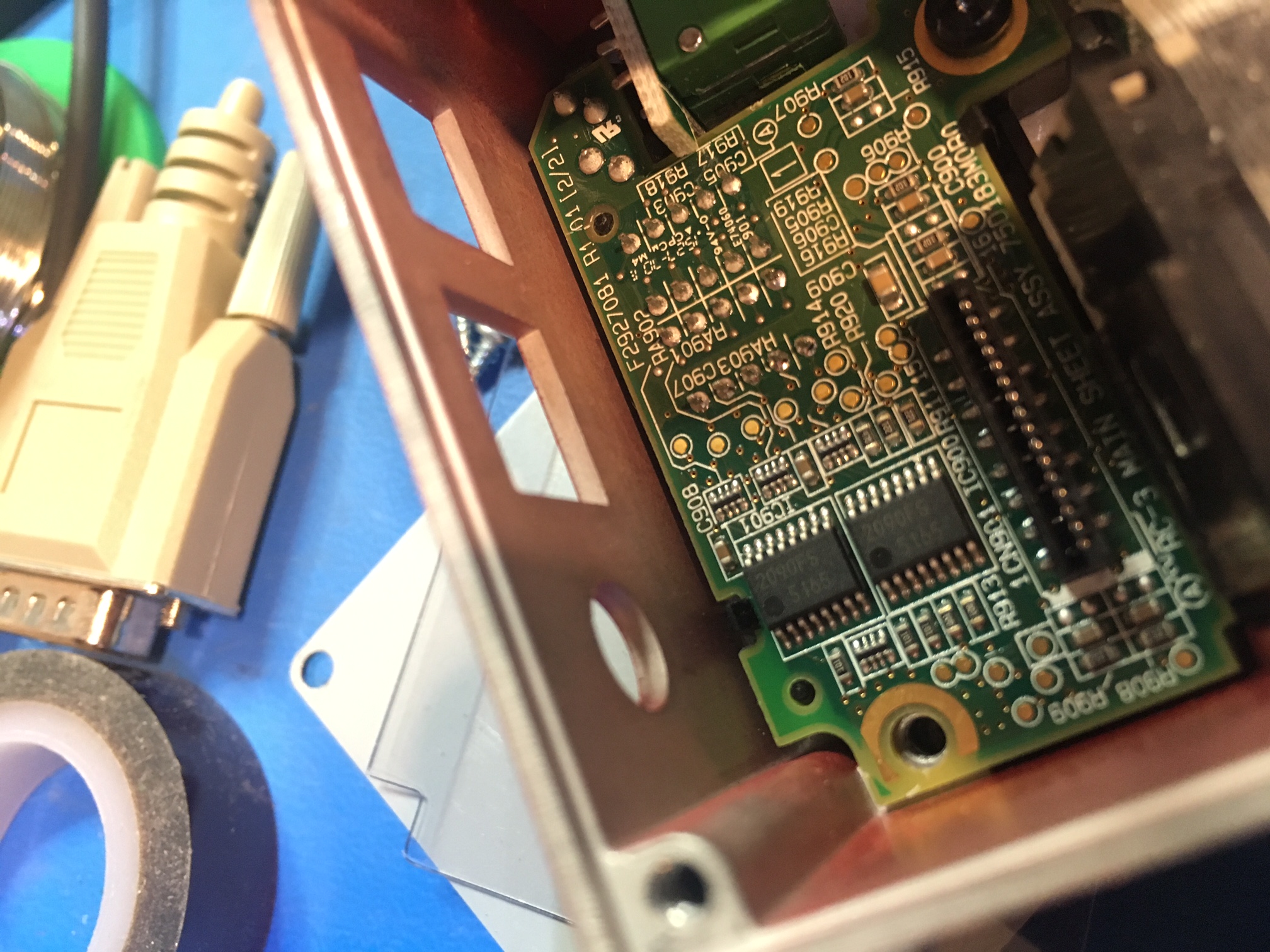
- This is a high enough quality product that they have test pads and are testing before they ship to you
- I now have something to solder to if I can figure out the correct connections.
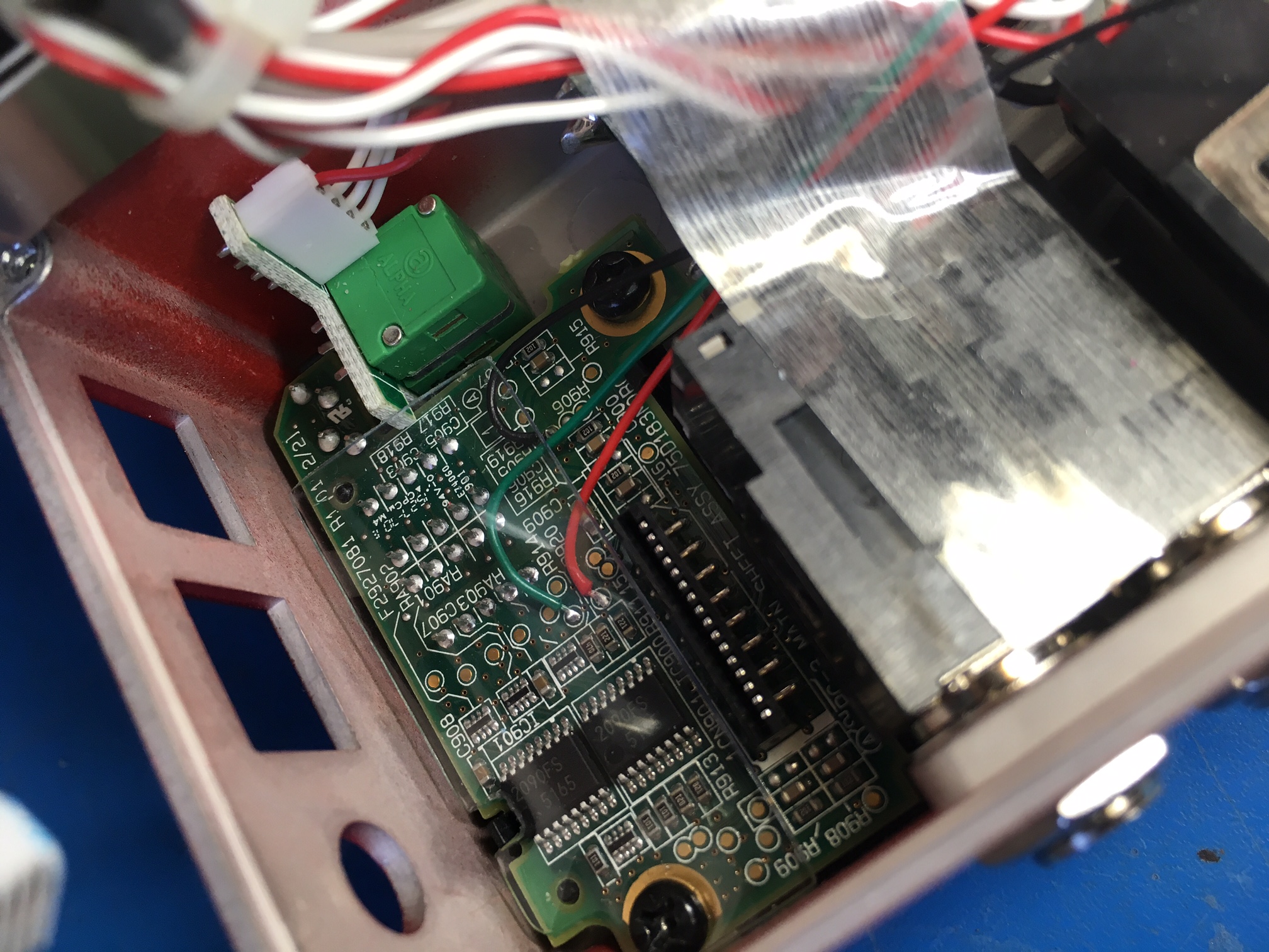
Here are the connections for red LED green LED and ground. We'll pull the power from a different area. I was getting concerned going in and out of the unit and worried about breaking a flex cable which would have been no fun.
So what kind of solution are we going to come up with? I'm a Microchip PIC programmer and design and build battery systems for a living, so lets use a microprocessor to do our dirty work!
The PIC I selected (PIC18LF13k22) has internal comparators. We can use these analog circuits to level-shift the LED signals so the PIC firmware can detect them.
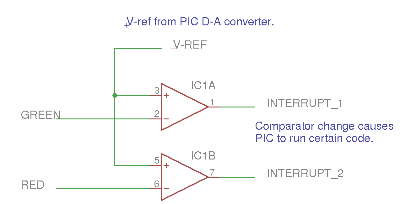
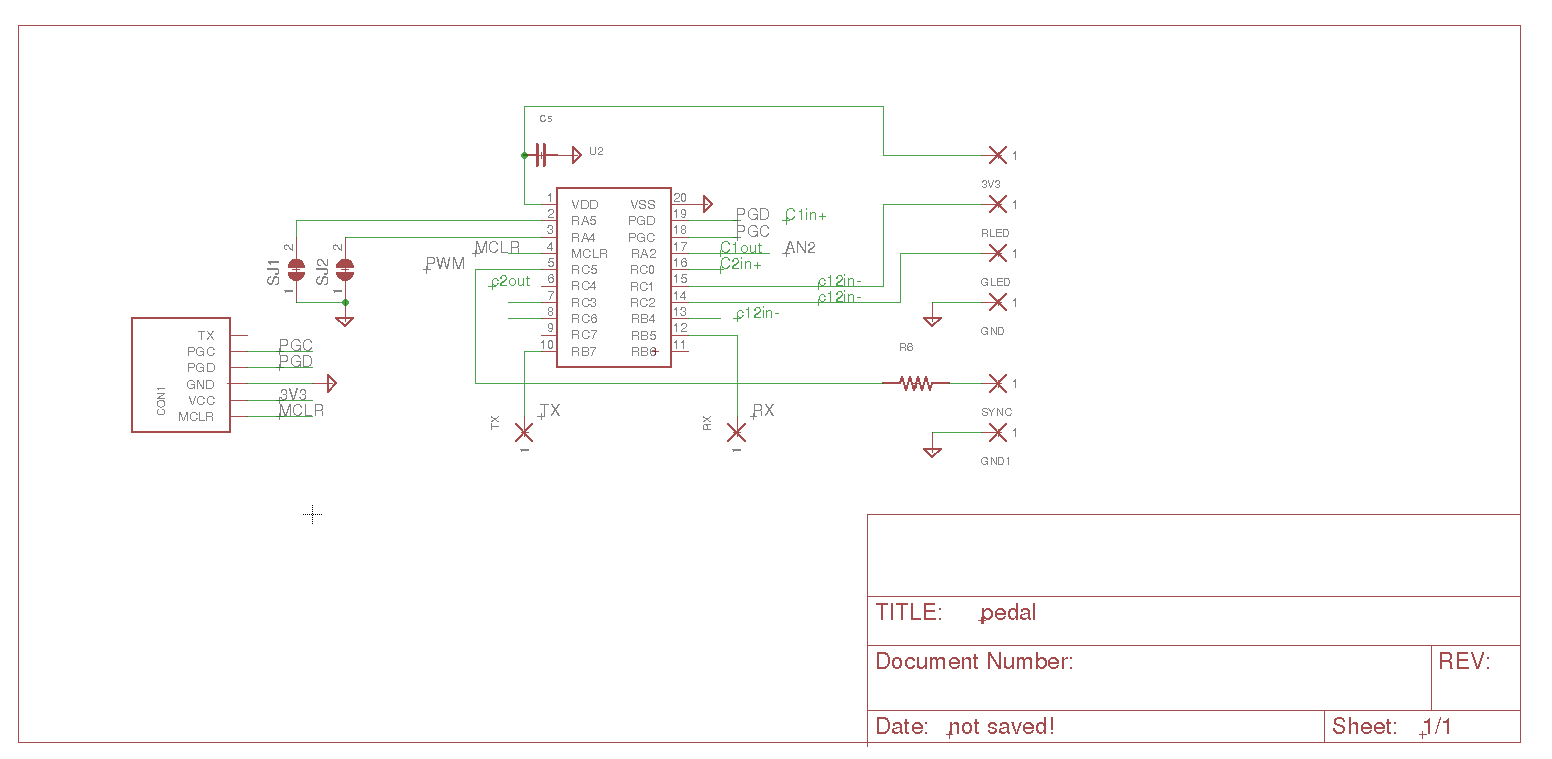
The entire schematic ends up looking like this:
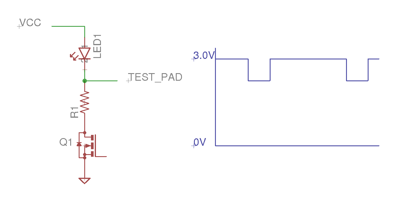
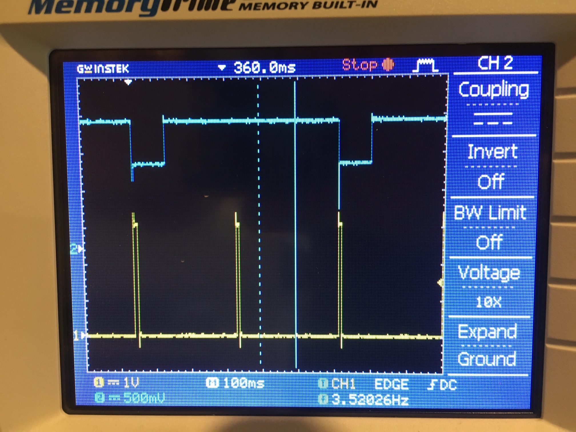
Input and output signals ended up looking like this:
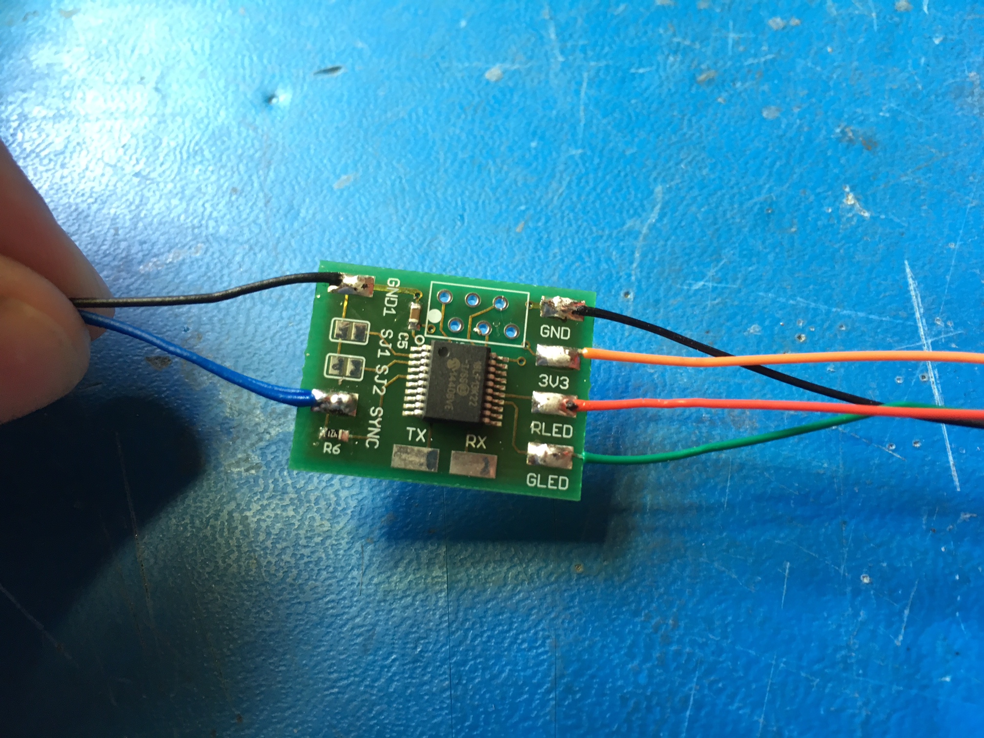
The final circuit board ended up looking like this:
Code was written. If you're big into that the files are at the end of this post. Basically the time between pulses from the LEDs is measured (any pulse from either LED) and that time is halved. A train of pulses is generated synced to the LED pulses but at twice the frequency.
A hole was drilled into the Boss pedal for the Sync jack (1/8" audio jack). Everything was mounted inside.

Bill Of Materials:
- 1.8" headphone jack. DigiKey Part Number: 839-1411-ND
- PIC18LF13k22
- Any 1K 0603 resistor to protect Sync from shorts.
- Any 2.2uF 10V 0603 Capacitor
- Thin wires harvested from an old serial port cable.